Overview
Position capture allows you to precisely determine what the motor position (or drive clock time) was when a specific event triggers. The AKD drive uses two independent captures, which operate similarly.
Position capture is used in precision environments, where the motor may be moving at very high velocities, an IO is triggered, and you must know exactly where the motor was when the event occurred. Homing algorithms often use position capture.
Position capture will capture the motor position (or drive clock time) when the capture trigger is activated. The position capture or drive lock time capture will happen in less than 3 microseconds of the input transition. This assumes the use of high speed input 1 or 2 with the filter turned off. The capture engine can be re-armed and ready for another capture in less than 62.6 microseconds. This capture engine allows the position capture to obtain more accurate results than those obtained using the scope or recorder clock.
Configuring Position Capture
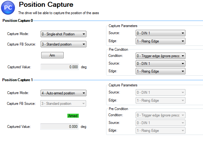
To configure the position capture, select Position Capture from the Settings group:
Setting the Capture Source (CAP0.FBSOURCE, CAP1.FBSOURCE)
CAP0.FBSOURCE and CAP1.FBSOURCE select the source of the captured value. Data for all source values is retrieved with CAP0.PLFB, CAP1.PLFB .
| Value | Description |
|---|---|
|
0 |
Captures from feedback 1 (FB1), independent of the value of PL.FBSOURCE. The units are the same as those used for PL.FB. |
|
1 |
Captures from feedback 2 (FB2). |
|
2 |
Captures from feedback 3 (FB3). |
|
3 |
Standard position capture, which stores PL.FB. The feedback number is determined by PL.FBSOURCE. |
| 4 | Captures from EXTENCODER.POSITION (AKD BASIC drives only). |
Setting the Trigger Source (CAP0.TRIGGER, CAP1.TRIGGER )
The trigger source determines which input on the drive causes the position capture to trigger.
| Option | Description |
|---|---|
| 0 - 6 | These options trigger on the Digital Input 1 pin through Digital Input 7 pin, respectively. |
| 7- 9 | These options trigger on the X9 connector RS485 Input 1 through RS485 Input 3, respectively. |
| 10 | This option triggers on the primary encoder index. |
Setting the Capture Mode (CAP0.MODE, CAP1.MODE )
The capture mode determines what information is saved on the drive when the capture triggers.
| Option | Description |
|---|---|
|
0 – Standard Position |
Captures the motor position in drive units. |
|
1 – Drive Internal Time |
Captures the time of the trigger in ns. |
|
2 – Distributed Clock Time |
Captures the network (Ethercat) distributed clock time. |
|
3 – Primary Encoder Signal |
Captures the motor postion triggering on primary encoder index. This mode automatically rearms after each trigger. |
If either 0 - Standard Position or 3 - Primary Encoder Signal is selected, delays may occur and are associated with feedback devices that are digital or interpolated .
Arming and Retrieving the Capture Value (CAP0.T, CAP1.T )
CAP0.EN arms the capture and CAP0.T retrieves the capture value. Once you have configured the capture, you must arm it before it will trigger. Click Arm (1) to arm the capture.
Once the capture is armed, when it triggers, the captured value will be displayed below the Arm button (2).
Setting the Capture Edge (CAP0.EDGE, CAP1.EDGE )
The capture edge determines which input state change triggers the capture.
| Option | Description |
|---|---|
|
1 – Rising Edge |
Captures when the input signal goes high, from a low state. |
|
2 – Falling Edge |
Captures when the input signal goes low, from a high state. |
|
3 – Both Edges |
Captures any time the input signal changes state. |
Setting the Pre-Condition Event: (CAP0.EVENT, CAP1.EVENT )
The Capture Pre-Condition Event gives the user more flexibility in setting what conditions must be present for the Capture to trigger.
| Event Option | Description |
|---|---|
|
0 – No precondition |
Capture triggers as soon as the capture edge occurs. |
|
1 – Trigger Edge after precondition |
Captures triggers only when the precondition occurs before the capture edge occurs. |
|
2 – Trigger Edge while precondition = 1 |
Captures triggers only while the precondition is evaluated and is true while the capture edge occurs. |
|
3 – Trigger Edge while precondition = 0 |
Captures triggers only while the precondition is evaluated and is false while the capture edge occurs. |
Setting up a Pre-Condition for complex capture
Setting the Precondition Edge: (CAP0.PREEDGE, CAP1.PREEDGE )
The pre-edge determines what input state change triggers the precondition. This feature operates the same as the capture edge described above.
Setting the Pre-Condition Select: (CAP0.PRESELECT, CAP1.PRESELECT )
The preselect chooses what input source will trigger the precondition (based on the preedge setting, and the prefilter setting). This feature operates the same as the capture source described above.
Kollmorgen Test Reports
Position Capture test report based on performance testing by Kollmorgen:
Capture Accuracy with External Sensor
Drive: AKD-T00306-NBAN-000
Motor: AKM-21C
Feedback Type: Incremental type 2048 line encoder
Digital Input used: DIN1  (high speed input)
DIN1.FILTER = 0  (very important to set this to zero so filtering does not delay the system response)
Sensor Used : IDC RP1 type mounted directly to the shaft. Common industrial limit switch.
MOVE.RUNSPEED = 1000 RPM
With the motor running at above speed and the capture mechanism armed, the drive was able to capture the position within 30-70 counts (.17 - .40 degree) of accuracy or 27.5 – 64.0 micro sec.
Capture Accuracy with Internal Index from encoder
Drive - AKD-T00606-NBAN-000
Motor-AKM22G
Feedback Type – Incremental Encoder 2048 lines
MOVE.RUNSPEED = 1000 RPM
With the motor running at above speed and the capture mechanism armed, the drive was able to capture the position within 10-20 counts (.05 - .11 degree) of accuracy or 9.5 – 18.0 micro sec.
Related Parameters